Pemesinan CNC Presisi kanggo Bagian Gedhe: Carane Ngatasi Geseran Termal lan Njaga Toleransi Ketat
Yen sampeyan tau ngalami pigura struktural aluminium dawane 3 meter melengkung nganti 0,5 mm langsung sawisé dibukak klem, sampeyan wis ngerti kasunyatan sing atos: Pemesinan CNC bagean gedhe Ora mung babagan nduwé mesin milling gantry sing luwih gedhé. Iki dolanan sing béda banget, ing ngendi dinamika termal, gravitasi, lan pamulihan elastis aktif nglawan setelanmu.
Nalika nindakake format gedhe Pemborongan CNC Ing komponen cor abot, rumah rak baterei EV, utawa bulkhead aerospace, tantangan utama ngalih saka mbusak logam kanthi prasaja dadi ngatur stres internal lan ngontrol defleksi dinamis.
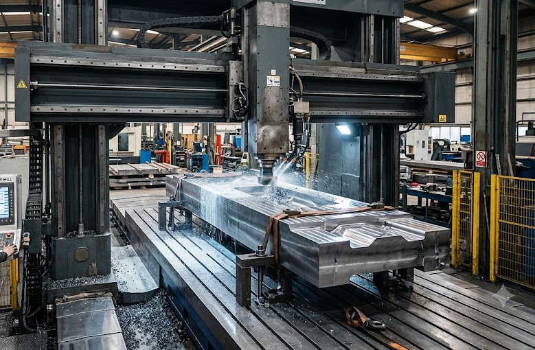
Ngatur ekspansi termal ing panggilingan CNC format gedhe
Ing komponen braket cilik, kenaikan suhu lantai bengkel nganti 3°C ora kroso babar pisan. Ing sambungan baja dawa 4 meter, kenaikan suhu sing padha ngembangake bahan nganti puluhan mikron—mesthi ngluwihi syarat ISO 2768-m utawa GD&T sing ketat.
Nalika nindakake Pemesinan CNC bagean gedhe, drift termal bisa ngrusak penjajaran bore kritis sadurunge pass finishing pungkasanmu rampung.
Strategi Real-Shop kanggo stabilitas termal:
- Panyelidikan ing Proses & Offset Koordinat Dinamis: Aja mung gumantung marang pangaturan WCS (Work Coordinate System) awalmu. Programake probe spindel otomatis (umpamane Renishaw) kanggo mriksa maneh datum lan dimensi fitur kritis antarane siklus roughing abot lan finishing entheng.
- Kasar, Istirahat, lan Santai: Penggerilan abot ngeculake panas gedhe menyang potongan kerja nalika ngeculake stres sisa ing pelat aluminium digulung utawa coran wesi duktil. Rough out 80% saka stok bahan, longgarkan klamp supaya logam bisa “ambegan” lan santai, banjur kencengake maneh nganggo torsi minimal sadurunge nindakake jalur panggilingan pungkasan.
- Pengiriman Cairan Pendingin sing Dikontrol: Pendingin banjir volume dhuwur mbantu, nanging kanggo bolongan kanthi kantung jero ing blok gedhe mbutuhake Pendingin Melalui Spindel (TSC, luwih saka 70 bar) kanthi tekanan dhuwur kanggo langsung mbilas serpihan lan nyegah akumulasi panas ing pinggir potong.
Penyangga Kerja Canggih: Nyegah Deformasi Penjepit ing Coran Abot
Ngejepit benda tempa seberat 500 kg mbutuhake gaya nyekel sing gedhe banget, nanging kakehan kenceng iku jebakan klasik. Gaya kenceng sing kakehan bakal ngowahi wangun benda kerja sacara elastis nalika mesin; sawise kowe ngeculake klem hidrolik, bagean kuwi bakal mbalèk kaya semula, lan toleransi rata-mu sirna.
Pambandingan: Klem Tradisional vs. Penahan Kerja Modern Tanpa Stres
| Fitur / Metrik | Penyepit mekanik tradisional / klem | Setelan Mengambang Nol-Titik lan Hidrolik |
| Bagéan Risiko Distorsi | Dhuwur (tekanan lokal nyebabake springback) | Sangat Rendah (distribusi gaya sing merata) |
| Wektu nyetel lan ngganti | 2,5 – 4,0 Jam | 15 – 30 menit |
| Penyerapan getaran | Lemah ing bagean sing tembene tipis | Dhuwur (nggunakake dongkrak sisih sing nyetel dhéwé) |
| Toleransi sing bisa digayuh | ±0,08 mm nganti ±0,15 mm | ±0,015 mm nganti ±0,03 mm |
Kanggo nyekel karya kanthi ajeg ing ranjang mesin gedhe:
- Sistem Klem Titik Nol: Ngurangi wektu nyetel kanthi drastis nalika njaga akurasi posisi sing bisa diulang nganti kurang saka 0,005 mm.
- Penyangga Apung Hidrolik: Pasang pin dhukungan hidrolik sing bisa nyetel dhéwé ing ngisor bagean témbok tipis kanggo nyuda geter lan nyegah alat geser (“让刀”).
- Piringan Grid Vakum kanggo Komponen Lembaran Gedhe: Ideal kanggo kulit aluminium aerospace gedhe ing ngendi klem ndhuwur mekanis bakal ngalangi jalur alat 5-sumbu.
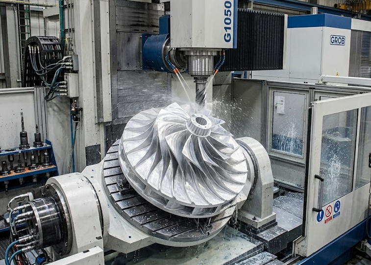
Optimasi Jalur Alat lan Penurunan Getaran kanggo Alat Jangkauan Daftar
Ngoperasikake face mill 50 mm ing ekstensi RAM 300 mm mbutuhake pendekatan sing beda banget tinimbang ngoperasikake VMC standar. Overhang sing dhuwur nyebabake cutter chatter, kegagalan insert karbida sadurunge wektune, lan asil permukaan sing ala ($R_a < 0.8 \ \mu\text{m}$).
- Pembersihan Adaptif (Pemesinan Kacepetan Dhuwur): Tinimbang motongan aksial jero kanthi keterlibatan ambane penuh, gunakna keterlibatan radial entheng ($a_e$) sing dipadu karo kedalaman aksial maksimal ($a_p$). Iki nuntun gaya motong munggah menyang spindel sing kaku tinimbang nyurung sacara horisontal marang penahan alat sing diulur.
- Pengaturan laju umpan dinamis: Ngurangi kecepatan umpan kanthi otomatis nalika mlebu radius internal sing sempit kanggo nyegah beban pojok lan deformasi pisau potong, supaya ora ana bekas chatter sing ala ing tembok kantong jero.
Pandhuan DFM: Carane Ngrancang Bagian Gedhe kanggo Pemesinan CNC sing Efisien Biaya
Yen sampeyan lagi nggoleki mitra manufaktur utawa ngrancang komponen abot khusus, ngelingi aturan Desain kanggo Manufaktur (DFM) iki bakal nyuda siklus mesin nganti 30%:
- Standarisasi radius pojok njero: Aja nggunakake sudut njero sing landhep 90°. Gawé radius kantong njero rada luwih gedhé tinimbang radius cutter standar (umpamane, gunakna radius 8 mm kanggo end mill 12 mm) supaya piranti mlaku lancar liwat pojokan tanpa mandheg.
- Ngombinasikake Permukaan Datum: Jaga supaya panggilan geometris kunci (tegak lurus, posisi, konsentrisitas) dirujuk marang siji bidang datum utama sing wis digarap ing setelan pisanan.
- Lebokake titik-titik angkat lan rigging: Lubang ulir M16 utawa M20 kanggo mata baut ora mung kanggo transportasi—tukang mesin butuh kanggo ngangkat billet mentah menyang meja mesin kanthi aman tanpa ngrusak permukaan presisi.
Pitakon sing Asring Ditakoni (FAQ)
Apa wae tantangan utama ing pangolahan CNC kanggo bagean gedhe?
Tantangan paling gedhé kalebu ngatur ekspansi termal, ngontrol deformasi pelepasan stres nalika mbusak bahan, ngindhari geter alat sing disebabake ekstensi spindel sing dawa, lan njaga toleransi posisi sing ketat ing saindenging sumbu perjalanan dawa (luwih saka 3 meter).
Kepiye carane mriksa toleransi ing komponen gedhe sing diolah nganggo mesin CNC?
Kita nggunakake pelacak laser portabel lan CMM jembatan gedhe (Mesin Pengukur Koordinat) ing njero ruang inspeksi sing dikontrol iklim ($20^\circ\text{C} \pm 0.5^\circ\textC)$) kanggo mriksa dimensi geometris kritis lan toleransi adhedhasar model CAD 3D.
Bahan apa sing biasane digunakake kanggo bagean CNC gedhe sing dipersonalisasi?
Bahan umum kalebu aloi aluminium struktural (6061-T6, 7075-T6), wesi tuang duktil (GGG40/GGG50), sambungan las baja abot (A36, Q355B), baja tahan karat (304/316L), lan aloi titanium kekuatan dhuwur kanggo aplikasi dirgantara.
Perlu mesin CNC presisi kanggo komponen gedhe sampeyan?
Apa sampeyan butuh pabrikan prototipe utawa produksi volume cilik kanggo mesin industri abot, fasilitas kita wis dilengkapi mesin bubut gantry 5-sumbu presisi dhuwur sing bisa nangani potongan kerja nganti dawane 4.000 mm.
Unggah file CAD 3D sampeyan (STEP/IGES) dina iki kanggo nampa ulasan DFM gratis lan penawaran rega sing kompetitif!